Electronics Design//
Introduction to Eagle
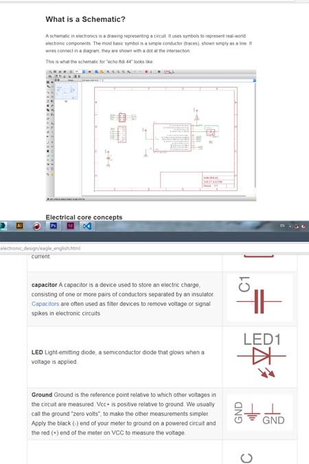
The first step was to download the free version of eagle from the original page and following the tutorial of fab academy. Since i am a beginner in electronics this tutorial explains step by step all the procedure. I opened and used the hello Echo example and i started to study all the different components, their uses and their combinations.
Installing the fab library
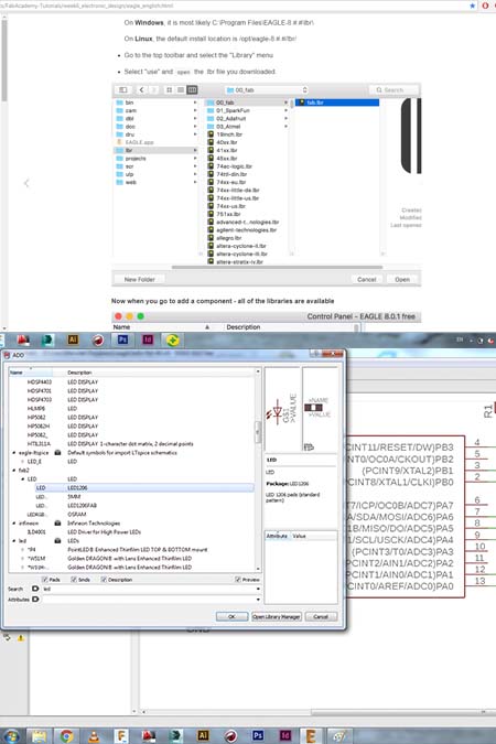
The next step, according to the tutorial was to download and to install the library of fab network. I faced some downloading problems in the beginning since i was not saving the file as a link. I used the rwaw file , i opened the code with notepad and i save it in the right way. Afterwards, i opened the library and all the elements i needed where there ready to be imported.I chose the elements according to the fab tutorial and the schematic.
Placing the right elements.
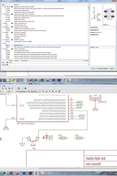
After studying and understanding the role of each elements and the combinations between them the following elements were placed : Resistor (value 10k) Purpose: pull-up resistor, button, ground, VCC, connect pin 10 (PA3) on the micro-controller to the button,LED (Light Emitting Diode) - LEDs have polarity, resistor.
Add and connect the elements.
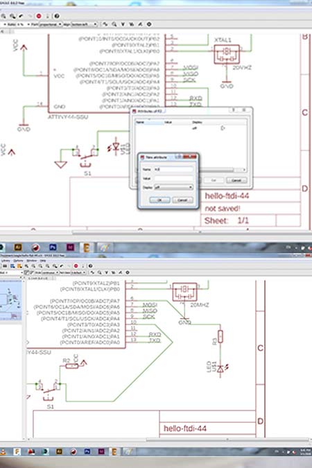
A very important thing after placing the right elemets is to give to them the right value and name. This could be useful if someone will choose to connect them just by tagging them. In this case i chose the direct connection to the right pin via a wire. I made the combinations and i wired them according to the tutorial of fab network and after studying a couple of other tutorials online. The result was a circuit with all the elemnts ans the connections accarding to the tutorials schematic.
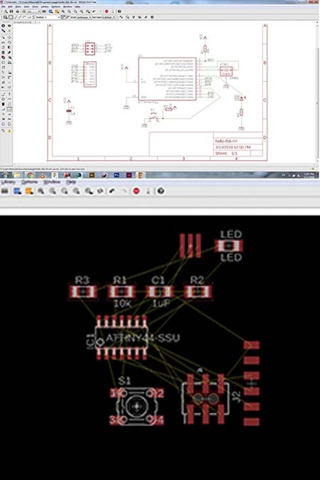
The final schematic and board design
The final schematic was resulted and in the picture above. The next step was to design the board. I pressed the switch to board button and a confused and complicated diagram appeared. As in the case of the schematic design the first thing to do was to get familiar with the software and undertand most of the commands.
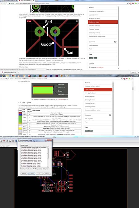
Automatic calculation
Being familiar with the software and the possibilities that gives you, helped me a lot to understand and check the connections between the elements. I tried first the automatic calculation mainly out of curiosity. As is obvious in the picture the automatic calculation didn't work in my case since some parts work but some other routes they are not connected or they overlapping with each other.
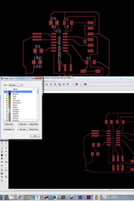
The final board
Since the automatic calculation was not giving the right results, i started to form manualy the board design. I followed the example of the fab network until one point and afterwards i formed in according to my needs (size ans style that will help me to shoulder it in the best way).Before i exported it as a png i deactivated all the layers apart from the first one.(connection layer.)
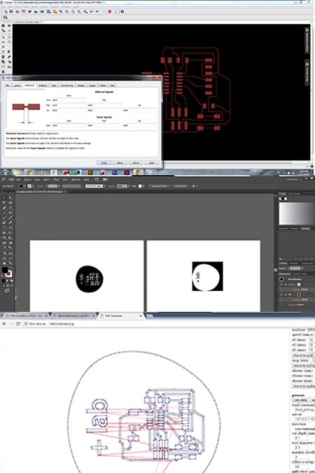
Preparation for milling
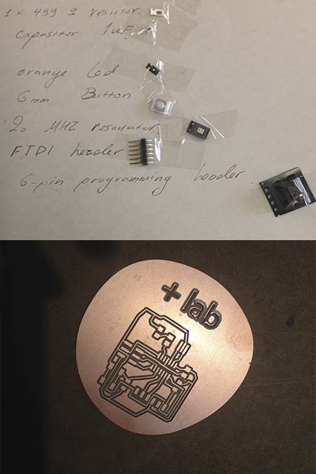
The final step was to import the specifications of the milling mashine we have at the lab (rolland mill, bits: 1/64 inch(for engraving) and 1/32 inch(for cutting)). This alternated the lineweight of our board as exactly as in the picture. Finally the board design was imported into illustrator/inskape, an alternative outline was added(my logo) and the formlabs.org calculated everything exactly as at the electronics production week.
 s
s
Milling the board
The board was milled exactly in the same way as in week 6.The components that was used was exactly the same elements that they were chosen in the schematic circuit.
Ready to be programmed
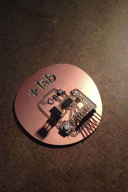
This time the shouldering was much easier and more detailed.After checking if the flow runs through all the right connections the board is ready to be programmed.
Fabduino
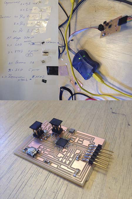
I always wanted to learn how to use the arduino and in this case my instructor proposed to create my own arduino, the fabduino. I created with a lot of pins so i can experiment in the future by adding aditional boards before i designed them and mill them as an indepent board. Exactly as an arduino.
Playing with arduino
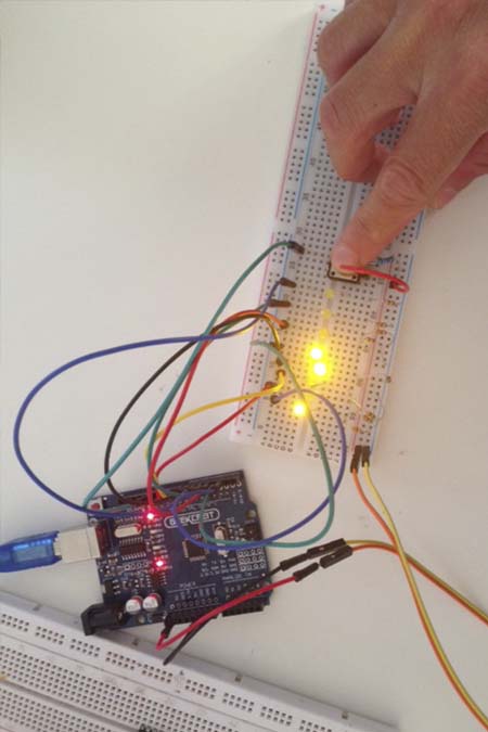
My first attemps in arduino where succesful ;-)